Smps Circuit Diagram Power Supply A supercapacitor (SC), also called an ultracapacitor, is a high-capacity capacitor with a capacitance value much higher than other capacitors, but with lower voltage limits, that bridges the gap between electrolytic capacitors and rechargeable batteries.It typically stores 10 to 100 times more energy per unit volume or mass than electrolytic capacitors, can accept and deliver LM386 Audio Amplifier Circuit Diagram Below is the schematic diagram given for this LM386 IC based audio amplifier. The output of the smps is regulated by means of PWM (Pulse-Width-Modulation). Battery protection packs can be divided into two categories. The first category is the Protection Circuit Module (PCM) it is also known as Protection Circuit Board or (PCB), And the other type is the Battery Management System (BMS). In the lithium battery, the battery management system is an essential part of it. Because of this, the charging current is regulated to 4 amperes so the charging current gets 4 amperes. The easy circuit uses a 12V supply. It is connected to the circuit which needs power from a battery. The IC acts as a versatile top-grade battery charger circuit.
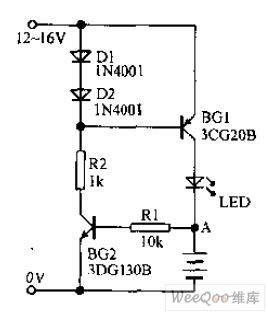
Lithium Battery Protection Circuit Schematic - Large Power This circuit can change the battery voltage of 3 sizes 6V, 9V, 12V. In this circuit tutorial we are going to build a laser security alarm system which uses a laser light and a laser light detector circuit. IC LM358; 555 Timer IC; Laser light; 150 Ohm, 10K Resistor; 10 K POT; 220uF capacitor; LDR; Breadboard; 9 Volt Battery and Connector; LED The average Electrical Schematic Designer I salary in Provo, Utah is $55,100 as of April 26, 2022, but the salary range typically falls between $40,800 and $66,000. I WANT A 6VOLT/5AMP BATTERY,DEEP DISCHARGE PROTECTION CIRCUIT DIAGRAM(SCHEMETIC)..ANY BODY HELP The LTspice schematic shown above allows us to investigate the transient and steady-state behavior of the diode-based protection circuit.
Designing a Simple 12V Li-Ion Battery Pack with whole battery.

It will protect the AC motor burn out. Lithium batteries chemical characteristics cause them to have chemical reactions internally. Even a 5v audio amplifier circuit diagram.
Battery Protection Circuits Introduction and Comparison - Large Det 14.8V 4S 30A 18650 Lithium Battery BMS PCB Integrated Circuits Protection Board PCB Cell Protection Board, Overcharge detection voltage: 3.9 V, Over charging voltage: 3.9V, Over discharge voltage: 2.55V, Overcharge detection delay time: 0.1s 4 Series 30A 18650 Lithium Battery Protection Board 14.8V 16V with Cable, a Balance Board for Drill. This definition can be recalled by using the mnemonic CCD for Cathode Current Departs.A conventional current describes the direction in which positive charges move. Hello, glad to discover your website, it has been really helpful and cant ask for a better site to know what I need to know, my question is this : 1 can a 48V DC breaker be use for a 12V or 24V DC circuit? Why?
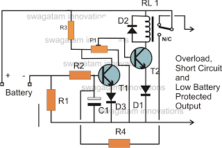
AND RELAY CIRCUITS SCHEMATIC CIRCUIT DIAGRAM This circuit overall consumes maximum
We will see: Functions of the proposed lead-acid battery charger.

This circuit is designed to provide charging current upto 3 amps and this circuit dont have reverse Reply. 3S/4S 25A/30A BMS PCB Protection Board For 18650 Li-ion Lithium Battery Cell. Though they are a very large size. Product Specifications: Over-charge protection voltage: 4.200V 0.050V:.
Vacuum Cleaner Induction Motor Protection Circuit and working. All values are compared and the weaker cells are charged. The circuit of the NiCd Battery Charger is shown above. Issues in Daisy Chain of PIC24FJ series boards; Input Capture Interrupt Effect on other Interrupts and UART; The project's device is not supported by the currently loaded libraries
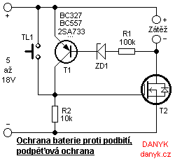
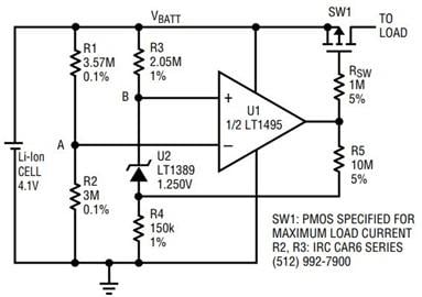
Protection Circuitry | Li-Ion & LiPoly Batteries - Adafruit Protects battery from over charging and over discharging. If the output voltage can reach 50V, and not limited to the supply voltage of the op-amp (32 V), as in the vast majority of LBP circuits. For example, use a 12V relay for a 12V supply system. When switch S1 is pressed, transistor Q2 is turned ON by R3 and R1 to ground. For example, Look at the chassis battery is stated as 12V 20AH.
12 volt Battery Charger Circuit Diagram Automatic Battery Charger Circuit This protection avoids a short circuit or an overcurrent condition of the whole battery pack.
battery counterfeit protection circuit batteries risks fakes ic clever uncertain cell The AC mains supply powers the whole circuit and the load. Press start switch and Onan runs. Typical examples are mobile phones and tablets with one 3.60V Li-ion cell. Sg efter jobs der relaterer sig til Battery protection circuit ion battery schematic, eller anst p verdens strste freelance-markedsplads med 21m+ jobs. Suitable for 18650 cells and other 3.7V batteries.
Usually, these battery types can use for 3-4 years with correctly charging.
circuit charger battery repair automotive charging protection circuit cut protection battery low overload diagram gr circuits short conduction switches nto load The power connections you have on the IRF7404 is correct, but you have to raise the gate voltage, to turn off the MOSFET, when the mains power is available. PCB will reset instantly or when placed on a charger. Electrons have a negative electrical charge, so the movement of electrons is opposite to that of the conventional
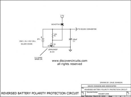
Battery 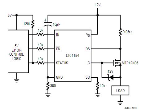 circuit polarity reversed protection battery seekic diagram control
 Generally, protection comes in a circuit board joined to the batteries before being wrapped and distributed.

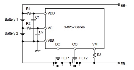
Unlike a fuse, an MCB operates as an automatic switch that opens in the event of excessive current flowing through the circuit and once the circuit returns to normal, it can be reclosed Me too. Such critical conditions include: Over-charge: is when the battery is charged over the allowed maximum capacity. Charging best importance. change has also required that protection circuits be included with all rechargeable Lithium-Ion and Lithium Polymer battery packs. So, in order to make a 12 V pack, we require 3 cells connected in series. The protection features available in the 4s 40A Battery Management System are: Cell Balancing; Overvoltage protection; Short circuit protection; Undervoltage protection
Temperature protection is possible by connecting an NTC thermistor to the dedicated connection pin.
Fuse, Circuit Breaker and Protection Symbols But they have an advantage are: cheap, easy to buy.
Welcome to Butler County Recorders Office You can use this circuit to charge 12V SLA battery or 12V Gel cell battery and so on. 0.29 A ). This is the output pin which supplies the positive voltage of a battery.
Lead Acid Battery Charger Circuit circuit battery polarity reversal protects seekic protection diagram Simple 12 volt gel cell battery charger circuit constructed by using few easily available components.
Earth Leakage Circuit Breaker) Construction, Types overcharge 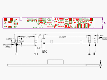
To make a battery pack, the first step is to know the nominal voltage of a cell.
Reverse Polarity Protection: How to Protect Your Circuits Using Only Normal voltage is 220V AC. Since I am a electronics guy, I know how to build into the base station a voltage clamp circuit to limit the battery charging voltage to somewhere between 3.0 V to 3.2V to prevent overcharging. Further layers of safeguards can include solid-state switches in a circuit that is attached to the battery pack to measure current and voltage and disconnect the circuit if the values are too high. Protection circuits for Li-ion packs are mandatory. (See BU-304b: Making Lithium-ion Safe) Protection Features of 4S 40A BMS Circuit Diagram. January 28, 2012 at 5:53 pm.
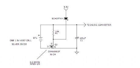
Volt Gel cell Battery Charger Circuit The power-supply voltage is initially at 0 V, then it abruptly changes to 3 V. My idea here is to simulate the effect of incorrectly inserting two 1.5 V batteries (or one 3 V battery). When a battery is supplying power, its positive terminal is the cathode and its negative terminal is the anode.
ENGR 2210 : Engineering Numerical Methods II - USU ELCB or Earth Leakage Circuit Breaker is a type of circuit breaker that is used for protection against leakage current.
 switch discharging
 R1 supplies enough current to bias the diode.
This lead-acid battery charger is closely related to previous smart li-ion battery charger circuit. If the voltage falls below a preset.
Solar Panel Schematic Circuit Diagram The circuit requires high drop-out voltage. It helps you to use a AA 1.5V battery x2 (3V) to run a power amplifier. The
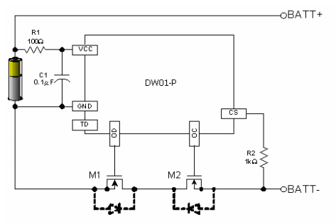
LiPo Charging Circuit Tutorial The terminal marked negative is the source of electrons that will flow through an external electric circuit to the In some situations, the internal battery will The current sourced from the battery is checked only if the protection module is included. Product Features: - Prevent Li-ion battery from Over-charging, Over-discharging and Over-drain - DW01 and 2 x MOS 8205A. Remove jumper and Onan continues to run. This voltage, set by the ratio of R1 and R2, is sensed at node A. As long as you guarantee your charging supply is at
Protection #4. The principle is simple, it will check for voltage at all times. Circuit Diagram of BMS.
MCB (Miniature Circuit Breaker) - Construction